
In aerospace and industrial testing, telemetry means one specific thing: measuring something at a location you cannot reach — a wing in flight, a shaft turning at 20,000 rpm, a rocket in ascent — and transmitting those measurements to somewhere an engineer can act on them. This article is about that discipline. It is not about patient monitoring in hospitals, and not about application performance monitoring in software, both of which have borrowed the same word.
Below: what telemetry data actually is, how a telemetry system is built, and how it is applied in flight test and on rotating machinery.
What is telemetry data?
Telemetry data is measurement data transmitted from a remote or inaccessible test article to a receiving station, usually over a radio link, for real-time observation and analysis.
The word comes from the Greek for remote measurement, and that is exactly the problem it solves. If you can run a cable to your sensor, you generally should — cabled measurement is cheaper and more robust. Telemetry exists for the cases where you cannot: because the test article is flying, because it is rotating, because it is kilometres away, or because it is going to be destroyed during the test.
Telemetry versus local data acquisition
The two are complementary, not alternatives:
- Local acquisition measures and stores data on the test article itself. Full sample rate, full channel count, recovered after the test. See our guide to data acquisition systems for how that chain works.
- Telemetry transmits a selected subset of that data, live, so decisions can be made while the test is running.
Bandwidth is why the subset exists. A radio downlink carries far less than an onboard recorder, so the test team chooses in advance which parameters matter in real time — typically safety-of-test parameters and the handful of measurements that decide whether to continue to the next test point. Everything else waits for the recorded data. That constraint is easing every year, though: modern telemetry campaigns routinely carry hundreds, and often thousands, of data signals, so the gap between what is transmitted and what is recorded keeps narrowing.
This is also why telemetry is not simply a nicer version of recording. Its value is timeliness: knowing now that a temperature is climbing towards a limit, rather than discovering it tomorrow in post-processing.
How a telemetry system works
A telemetry system is a chain, and every link constrains the ones after it:
1. Sensors
Strain gauges, accelerometers, thermocouples, pressure transducers, position sensors, etc., convert physical behaviour into electrical signals at the point of interest.
2. Signal conditioning
Excitation, amplification, filtering and isolation prepare those signals for digitising. On a rotating or vibrating article this stage does a great deal of work, because the electrical environment is hostile and the signals are small.
3. Encoding
Conditioned channels are digitised and assembled into a serial data stream with a rigid frame structure, so the receiving end can identify which bits belong to which measurement. In aerospace this framing follows the IRIG-106 family of standards — PCM framing, and increasingly packet telemetry — which is what allows equipment from different suppliers and different ranges to interoperate.
4. RF transmission
The encoded stream modulates a radio carrier, typically in the S, C or L bands for aerospace flight test. Transmit power, antenna pattern and modulation scheme are traded against link margin, range and the spectrum actually licensed to the test range.
5. Receiving station
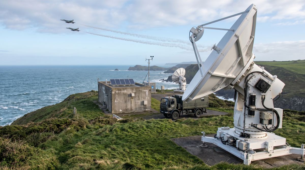
Tracking antennas follow the test article, receivers demodulate the carrier, and best-source selection combines multiple receive paths to produce a single clean stream — because no single antenna output keeps a perfect link through an entire flight profile. For certain applications, our tracking antennas handle two- or three-band operation from a single aperture, which removes a second antenna from the site.
6. Decommutation and display
The stream is decommutated: unpacked back into individual parameters, converted to engineering units and presented on real-time displays, while being recorded for post-flight analysis.
In practice these split into two procurement streams — the onboard telemetry chain that has to survive the test environment, and the ground telemetry chain that has to acquire and hold the link.
Those two streams usually sit with different organisations. The onboard chain is specified and procured by whoever designs or builds the test article — an aircraft manufacturer, for example — while the ground chain belongs to the test site. Only the very largest manufacturers operate their own range, so most programmes run on an agreement between the two parties, and the interoperability that IRIG-106 provides is what makes that agreement workable.
Telemetry in flight test
Flight test is the classic application, and the one that drove most of the standards. A flight test telemetry installation transmits a selected parameter set from the aircraft to a ground station so that the flight test engineer, the safety officer and the test director can watch the aircraft’s behaviour as it happens.
What makes it demanding is not the radio link in isolation, but the combination of constraints:
- Link continuity through manoeuvres that put the airframe between the transmit antenna and the ground station.
- Weight and space, competing with every other system on a test-instrumented aircraft.
- Environmental qualification for vibration, temperature and altitude — and, on supersonic articles, for aerodynamic heating.
- Bandwidth discipline, since the parameter list always wants to grow and the spectrum allocation does not.
The same architecture scales down to unmanned platforms and rockets, and up to multi-site ranges with redundant links — where telemetry is one input among tracking, optical and command systems within a broader flight test instrumentation programme.
Telemetry from rotating machinery
The second major application is measuring on something that turns. Here the obstacle is not distance but rotation: a strain gauge bonded to a rotating shaft, blade or gear cannot be wired to a stationary amplifier without something crossing the boundary between rotating and stationary frames.
Rotating telemetry solves this by putting the measurement chain on the rotating part itself. A compact transmitter module mounts directly on the shaft, rotor or disc; it excites the sensors, conditions and digitises the signals, and transmits them across a short air gap to a stationary receiver. Power is typically supplied inductively across the same gap, so no physical contact is required, although other battery-based solutions may be available too depending on the application.
The engineering constraints are severe and specific: the module must survive high centrifugal loading, tolerate high temperatures near hot sections, fit inside whatever space the mechanical design leaves available, and be balanced well enough not to disturb the very dynamics being measured.
Aerospace engine and turbine testing
Blade strain, disc temperature and shaft torque during development and certification testing — measurements that determine service life and cannot be inferred reliably from stationary instrumentation.
Helicopter rotor testing
Rotor blade loads, pitch link forces and hub moments, on an assembly that is simultaneously rotating, flapping and lagging. Rotating telemetry is often the only practical route to these measurements.
Wind turbine testing
Wind turbine testing applies the same principle at a different scale: blade root bending moments, main shaft torque and pitch system loads, measured on rotors tens of metres across, both on test stands and on operating machines.
Automotive powertrain testing
A substantial share of rotating telemetry work is automotive. Torque and strain measurement on e-drives, transmissions, gearboxes and clutches — on dynamometers and in vehicle testing — supports efficiency optimisation, durability validation and NVH investigation. Electrified powertrains have increased demand here, because the torque characteristics of an electric drive differ fundamentally from a combustion engine and the validation data has to be measured rather than assumed.
Across all four, the measurement chain is the same one described above, compressed into a package that can spin. Our rotating telemetry systems cover turbines, engines, shafts, rotors, gearsets and powertrains in high-G, high-RPM and high-temperature test environments.
Choosing a telemetry system
The specification usually resolves to six questions:
- How many channels, and of what type? Bridge sensors, thermocouples and accelerometers each impose different conditioning requirements.
- What bandwidth do you actually need? Sample rate multiplied by channel count multiplied by resolution sets the required data rate, which drives everything downstream.
- What is the environment? Rotational speed, temperature, vibration and available space rule options out quickly.
- What range and link margin? A test cell and a 200 km range are different problems.
- Which standards apply? In telemetry flight testing, IRIG-106 compliance is mandatory for interoperability with existing range infrastructure.
- Real time, recorded, or both? Most serious campaigns are both, and the split between them should be a deliberate decision.
Frequently asked questions
What is the difference between telemetry and data acquisition?
Data acquisition measures and digitises signals; telemetry transmits them to a remote receiver. Most test installations do both — recording at full rate on the test article while transmitting a reduced parameter set live. Telemetry answers the question of what is happening now; recorded acquisition answers what happened, in full detail, afterwards.
What is telemetry used for in engineering?
Monitoring test articles that cannot be cabled: aircraft and rockets in flight, rotating shafts and rotors, remote or hazardous installations, and destructive tests. Its purpose is to enable decisions during the test — continuing, aborting or adjusting — rather than only after it.
How is data transmitted from a rotating shaft?
A transmitter module mounted on the rotating component conditions and digitises the sensor signals, then transmits them by short-range radio across a small air gap to a stationary receiver. Power is normally delivered inductively across the same gap, so the system requires no physical contact and no maintenance of wearing parts.
What frequency bands does aerospace telemetry use?
Predominantly the S, C and L bands, with the specific allocation depending on national spectrum regulation and the range being used. Band choice affects antenna type, propagation and available bandwidth, and is usually constrained by what the range is licensed to operate.
Can rotating telemetry instrumentation be used on operating equipment, not just test articles?
Yes. The same rotating telemetry principle applies to in-service monitoring of turbines, gearboxes and drivetrains where continuous load or temperature data supports condition monitoring and life extension, though instrumentation for permanent installation carries different reliability and certification requirements from test instrumentation.
Discuss your telemetry requirement
Sensicore supplies complete telemetry chains for aerospace and industrial testing: onboard and ground telemetry for flight test campaigns, and rotating telemetry for engines, turbines, rotors and powertrains. Explore our onboard and ground telemetry and rotating telemetry ranges, or contact our engineering team to discuss your test campaign.