
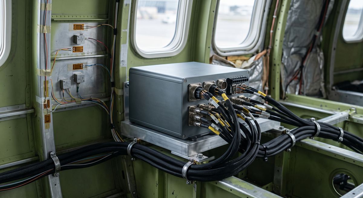
Every test campaign — a prototype aircraft on its first flight, an e-drive on a dynamometer, a turbine on a test stand — generates physical phenomena that nobody can see directly: strain in a spar, pressure in a combustion chamber, temperature on a bearing, vibration in a gearbox. A data acquisition system is what turns those phenomena into numbers an engineer can visualise, analyse, compare against a requirement, and defend in a design review or a certification audit.
This guide explains what a data acquisition system is, what it is built from, the main types used across industry and aerospace, and the specifications that actually decide whether a system fits your programme.
What is a data acquisition system?
A data acquisition system — commonly shortened to DAQ system or DAS — is the chain of hardware and software that measures physical quantities using sensors, converts those measurements into digital values, and records or transmits them for analysis.
The definition sounds simple, but the engineering is not. A DAQ system has to preserve the integrity of a signal that may be a few microvolts, in an environment that may be vibrating at 20 g, at 150 °C, several metres from the recorder, while remaining time-correlated with dozens or hundreds of other channels to within microseconds. Everything else in the specification follows from those constraints.
It is worth separating two ideas that are often confused:
- Data acquisition is the act of measuring and digitising. The data ends up stored on, or streamed from, the unit doing the measuring.
- Telemetry is the transmission of that data to a remote location, typically over a radio link, so it can be observed, processed and recorded while the test is running.
The two frequently coexist: a test article may record everything on board at full rate and simultaneously transmit a reduced set of parameters to the ground so the test team can make safety decisions in real time.
The signal chain: from sensor to data
Every DAQ system, from a two-channel bench setup to a full flight test installation, is a variation on the same signal chain:
- Sensor or transducer converts a physical quantity — force, strain, pressure, temperature, acceleration, displacement — into an electrical signal.
- Signal conditioning prepares that signal for digitising: excitation for bridge sensors, amplification, filtering, isolation and linearisation.
- Analogue-to-digital conversion samples the conditioned signal at a fixed rate and turns each sample into a number.
- DAQ hardware timestamps, packetises, stores and forwards the digitised channels.
- Analysis software converts raw counts into engineering units, applies calibrations, and produces the plots and reports the test engineer actually works with.
A weakness at any point limits the whole chain. A 24-bit converter behind a poorly grounded bridge amplifier will faithfully record noise at very high resolution — an expensive way to measure nothing.
Core components explained
Sensors and transducers
The measurement starts here, and so does the error budget. Strain gauges and load cells measure force and deformation; accelerometers capture vibration and shock; thermocouples and RTDs cover temperature; pressure transducers handle static and dynamic pressure. In airborne flight sensing, static and Pitot tubes provide airspeed and aerodynamic pressure data, while displacement sensors, gyroscopes, and GPS/GNSS receivers complete the picture by tracking position, motion, attitude, and trajectory.
Selection is driven by application type, range, required accuracy, frequency response and the environment the sensor has to survive.
Signal conditioning
The stage that most often decides data quality. Bridge-based sensors need a stable excitation voltage and precise amplification. Anti-aliasing filters must remove content above half the sampling rate before digitising, because once aliasing has occurred no amount of post-processing will undo it. Isolation prevents ground loops between a test article and the instrumentation, which in a large installation is a routine source of corrupted data.
Analogue-to-digital conversion
Resolution defines how finely the signal is divided; sampling rate defines how fast it is captured. A common rule of thumb is to sample at five to ten times the highest frequency of interest — well above the theoretical Nyquist minimum — so transients keep their shape rather than merely being detected.
DAQ hardware and recording
The acquisition unit itself: channel count, on-board storage, interfaces, power consumption, and the mechanical and environmental qualification it carries. In airborne and vehicle-mounted work this is where size, weight and ruggedisation become as important as the electrical specification.
Software
Configuration, calibration management, real-time display and post-processing. On a large campaign the software decides how quickly a team can go from raw file to answer — often the difference between one test point per day and five.
Types of data acquisition system
DAQ is not a single product category. The same underlying signal chain is packaged very differently depending on where it has to work:
| Type | Where it is used | Defining characteristic |
|---|---|---|
| Laboratory / benchtop | R&D labs, component testing, calibration | Highest channel density and accuracy; mains powered; benign environment |
| Ground and test-stand | Engine and turbine test cells, structural rigs, dynamometers | Long cable runs, high channel counts, continuous operation |
| Distributed | Large structures, ranges, multi-station installations | Acquisition close to the sensors, synchronised across nodes over a network |
| Onboard / airborne rugged | Flight test, vehicles, rotating and moving assemblies | Size, weight and power constrained; qualified for vibration, temperature and altitude |
At Sensicore we supply data acquisition across all of these categories — laboratory, ground, distributed and onboard — for aerospace, automotive, defence, naval and other programmes, and for activities ranging from development testing, validation and certification campaigns to upgrades, MRO, and engine and turbine testing. The architectures below are where the requirements diverge most sharply.
Distributed acquisition and non-intrusive installation
On a large test article, running hundreds of sensor cables back to a central rack adds weight, installation time and failure points. Distributed architectures place compact acquisition units near the sensors and network them together with a common time base. Where the structure cannot be modified at all — no drilling, no permanent harnessing — non-invasive acquisition kits clamp onto the structure and stream data wirelessly, which keeps a programme on schedule when instrumentation access is the constraint.
Modular and rugged acquisition
Test programmes change. Modular systems let a team reconfigure channel types and counts between test points instead of specifying a fixed system up front, and rugged FTI kits package that flexibility for constrained, harsh environments where a laboratory chassis would not survive the first sortie.
Rotating instrumentation
A rotating assembly cannot be cabled to a stationary acquisition unit, so the acquisition moves onto the rotating part itself. A compact transmitter mounted on the shaft, rotor or disc excites the sensors, conditions and digitises the signals, and transmits them across a short air gap to a stationary receiver. It is a data acquisition system of the telemetry type, built specifically for rotating machines — engines, turbines, gearboxes and powertrain — where the alternative is no measurement at all. Our rotating telemetry systems cover wireless torque and strain measurement in high-G, high-RPM and high-temperature test environments.
Key specifications that actually matter
Datasheets are long. In practice a small number of parameters decide whether a system works for a given campaign:
- Sampling rate per channel. Check whether the quoted rate is per channel or shared across a multiplexed input bank — the difference is easy to miss and expensive to discover late.
- Resolution and effective number of bits. A 24-bit converter with 18 effective bits of noise-free resolution is, in practice, an 18-bit system. Where the effective figure is published, compare candidates on that rather than on nominal resolution alone.
- Channel count and mix. Not just how many, but how many of each type — bridge, thermocouple, ICP, voltage, digital.
- Synchronisation. On multi-unit installations, the time alignment between units determines whether cross-channel analysis such as modal or order tracking is possible at all. This is the specification most often overlooked and hardest to retrofit.
- Environmental qualification. Operating temperature range, vibration and shock levels, altitude, ingress protection and EMC. In airborne work these frequently eliminate more candidate systems than the electrical specification does.
- Size, weight and power. On a flight test article or a rotating assembly, every gram and every watt is contested.
Data acquisition in flight test instrumentation
Flight test is the most demanding application of data acquisition, because every constraint applies at once: microvolt signals, severe vibration, wide temperature swings, strict weight limits, and data that must be trusted well enough to clear an aircraft for the next test point.
A flight test instrumentation installation typically combines onboard acquisition units, sensors distributed across the airframe and systems, an accurate time reference, and onboard recording — with an optional radio downlink to the ground.
That optional downlink is the key architectural decision, and DAQ has a role in both cases:
- Non-telemetry campaigns. All data is acquired and recorded on board, then recovered and analysed post-flight. The acquisition system’s storage capacity, robustness and data integrity carry the whole campaign.
- Telemetry campaigns. Data is acquired on board and simultaneously transmitted to a ground station so the test team can monitor parameters live and make go/no-go decisions during the flight. Typically a telemetry campaign carries hundreds, if not thousands, of data signals. Here the acquisition system also has to feed an encoder and transmitter within a fixed bandwidth budget. The onboard and ground telemetry chain is the subject of its own discussion.
In both cases the data originates in sensors installed on the test vehicle — whatever is flying and being tested: aircraft, helicopter, rocket or unmanned platform. Those sensors are part of the same supply problem as the acquisition units themselves, and are covered by our aerospace flight testing sensor range.
Beyond the test article, range-level installations add another layer: mission control, data processing and simulation systems that aggregate acquisition, tracking and telemetry into a single operational picture, which is the role of test range equipment. And where the parameters being acquired are avionics bus traffic rather than analogue signals, the acquisition problem becomes a protocol problem — see our guide to how the ARINC 429 data bus works.
How to choose: a practical checklist
Before specifying a system, answer these:
- What are you measuring, and to what accuracy? Work backwards from the required measurement uncertainty, not forwards from an available product.
- What is the highest frequency of interest? This sets the sampling rate and the anti-aliasing requirement.
- Where does the system have to live? Temperature, vibration, altitude and available power eliminate options quickly.
- How many channels, of which types, and will that change? Modularity costs money up front and saves it across a campaign.
- Do you need results during the test, or after it? This decides whether telemetry is required, and how much bandwidth.
- How will the data be processed? File formats, calibration handling and integration with existing analysis tools are routinely underestimated.
Frequently asked questions
What is the difference between a DAQ system and a data logger?
A data logger is a simple, usually self-contained device that records measurements at relatively low rates for later download. A DAQ system is a broader architecture: higher sampling rates, precise multi-channel synchronisation, configurable signal conditioning, and typically real-time output. Loggers suit long-duration environmental monitoring; DAQ systems suit dynamic testing where transients and cross-channel timing matter.
How many channels do I need?
Count the measurement points required by the test matrix, then add margin for the instrumentation that always gets added mid-campaign — reference channels, redundant sensors on critical points, and parameters someone asks for after the first results. Modular systems handle that growth without a new procurement cycle.
What sampling rate is enough?
Application dependent. As a rule of thumb, sample at five to ten times the highest frequency of interest, rather than the theoretical minimum of twice. Nyquist tells you what can be reconstructed in principle; practical transient analysis needs enough points to preserve the shape of the event, not merely detect it.
Can one system cover laboratory and flight testing?
Partly. A common software environment and consistent data formats across laboratory, ground and airborne systems may be achievable and genuinely valuable, because they let one analysis toolchain serve the whole programme. The hardware itself usually differs: airborne units trade channel density for weight, ruggedisation and qualification.
Do I need telemetry as well as acquisition?
Only if decisions for your application have to be made while the test is running. Safety-critical flight testing generally requires a live downlink; a structural fatigue rig usually does not. Telemetry adds cost, weight and spectrum management, so it should be a deliberate requirement rather than a default — but sometimes it is the only way to go. Telemetry shall be employed, for example, in certification campaigns for aircraft or in space launch campaigns.
Specify your acquisition system with us
Sensicore supplies data acquisition systems and instrumentation for laboratory, ground, distributed and airborne testing across aerospace, automotive, defence and naval programmes — from individual sensors to complete instrumented test campaigns. Explore our flight test instrumentation range and sensors and specific instrumentation, or contact our engineering team to discuss your measurement requirements.